- -4.072″
- -Numbered Connection
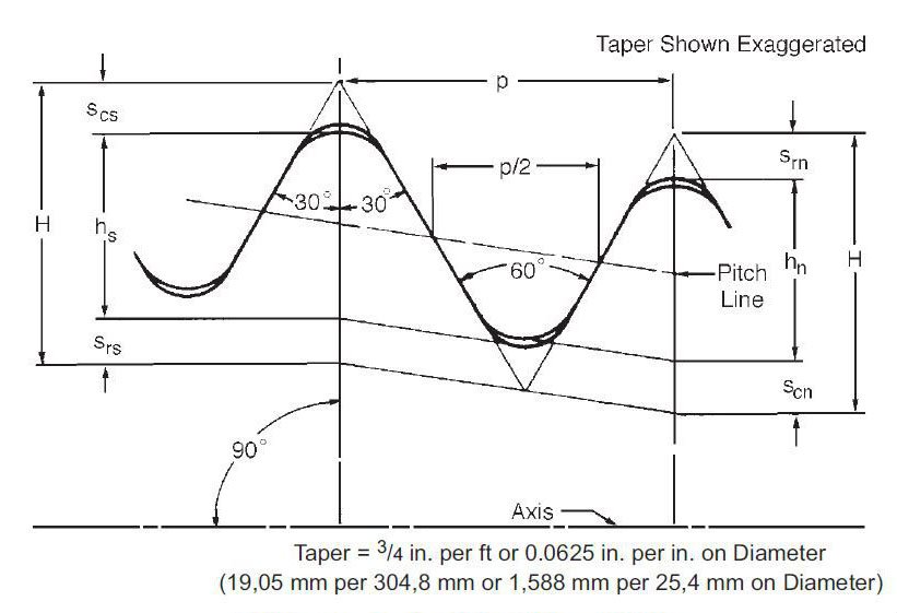
- -V-038R Thread Form
- -4 TPI (Threads per Inch)
- -2″ TPF (Taper per Foot)
- -60 deg included angle
[bg_collapse view=”button-red” color=”#f0f8ff” expand_text=”▼Thread Form” collapse_text=”▲Thread Form” inline_css=”width: 100%” ]
[/bg_collapse]
[bg_collapse view=”button-red” color=”#f0f8ff” expand_text=”▼Lead” collapse_text=”▲Lead” inline_css=”width: 100%” ]
| Measurement Interval | 1″ |
| Measured Nominal Value | 0 |
| Compensated Lead Parallel to Taper | 0.2509″ |
| Compensated Setting Value¹ | 1.01379″ |
| Flat Setting Value² | 0.86979″ |
| Contact Point Size | .144″ |
| Tolerance | +/-.0015″ |
¹Lead is typically measured over 1″ intervals. Since the threads are on a taper, the 1″ value must be compensated to account for the taper. This value is the compensated value to account for the taper of the threads.
²The flat setting value is for using Gauge blocks to set the gauge. This value is calculated from the compensated setting value.
[/bg_collapse]
[bg_collapse view=”button-red” color=”#f0f8ff” expand_text=”▼Taper” collapse_text=”▲Taper” inline_css=”width: 100%” ]
| Taper Callout | 2″ Taper per Foot |
| Measured Nominal | 0.1667 in./in. |
| Compensated Setting | Set on part³ |
| Setting Standard | N/A |
| Contact Point Size | .144″ |
| Tolerance | +0.0025″ |
³Taper gauges take direct measurements. You mark the part, set the gauge on the part and measure in intervals on the part. Each measurement interval is determined by your connection TPI. This interval would be 8 threads. *Always count the first marked thread as zero and count the roots of the thread when marking the part. *For external connections, you will set your gauge on the first marked thread closest to the face then measure upward to the next marked thread.
[/bg_collapse]
[bg_collapse view=”button-red” color=”#f0f8ff” expand_text=”▼Thread Height” collapse_text=”▲Thread Height” inline_css=”width: 100%” ]
| Truncated Thread Height | 0.122″ |
| Measured Nominal | 0 |
| Setting Standard “U” groove depth | 0.1216″ |
| Contact Point Size | 0.072″ |
| Tolerance | +.001″/-.002″ |
[/bg_collapse]
[bg_collapse view=”button-red” color=”#f0f8ff” expand_text=”▼Pitch Diameter” collapse_text=”▲Pitch Diameter” inline_css=”width: 100%” ]
| Pin Cylinder Diameter | 4.156″ |
| Pin Cylinder Diameter Tolerance | +/-.016″ |
| Distance to Gauge Plane | .0625″ |
| Pitch Diameter at Gauge Plane | 4.072″ |
| Set to Flat Pitch Diameter at Gauge Plane | TBD |
| Contact Point Size | .144″ |
| Pitch Diameter Tolerance | -.001″/+.002″ |
[bg_collapse view=”button-blue” color=”#f0f8ff” expand_text=”▼Thread Form” collapse_text=”▲Thread Form” inline_css=”width: 100%” ]
[/bg_collapse]
[bg_collapse view=”button-blue” color=”#f0f8ff” expand_text=”▼Lead” collapse_text=”▲Lead” inline_css=”width: 100%” ]
| Measured Interval | 1″ |
| Nominal Measured Value | 0 |
| Compensated Lead Parallel to Taper | 0.2509″ |
| Compensated Setting Value¹ | 1.01379″ |
| Flat Setting Value² | 0.86979″ |
| Contact Point Size | .144″ |
| Tolerance | +/-.0015″ |
¹Lead is typically measured over 1″ intervals. Since the threads are on a taper, the 1″ value must be compensated to account for the taper. This value is the compensated value to account for the taper of the threads.
²The flat setting value is for using Gauge blocks to set the gauge. This value is calculated from the compensated setting value.
[/bg_collapse]
[bg_collapse view=”button-blue” color=”#f0f8ff” expand_text=”▼Taper” collapse_text=”▲Taper” inline_css=”width: 100%” ]
| Taper Callout | 2″ Taper per Foot |
| Measured Nominal over 1″ interval | 0.1667 in./in. |
| Compensated Setting | Set on part³ |
| Setting Standard | N/A |
| Contact Point Size | .144″ |
| Tolerance | -0.0025″ |
³Taper gauges take direct measurements. You mark the part, set the gauge on the part and measure in intervals on the part. Each measurement interval is determined by your connection TPI. This interval would be 8 threads. *Always start marking the part from the first fully-formed thread closest to the face of the part. When marking, count the first marked thread as zero and count the roots of the thread when marking the part. *For internal connections, you will set your gauge on the innermost marked thread then measure outward to the next marked thread.
[/bg_collapse]
[bg_collapse view=”button-blue” color=”#f0f8ff” expand_text=”▼Thread Height” collapse_text=”▲Thread Height” inline_css=”width: 100%” ]
| Truncated Thread Height | 0.122″ |
| Measured Nominal | 0 |
| Setting Standard “U” groove depth | 0.1216″ |
| Contact Point Size | .072″ |
| Tolerance | -.003″/+.001″ |
[/bg_collapse]
[bg_collapse view=”button-blue” color=”#f0f8ff” expand_text=”▼Pitch Diameter” collapse_text=”▲Pitch Diameter” inline_css=”width: 100%” ]
| Total Box Depth | 5.125″ |
| Total Box Depth Tolerance | +0.38″ |
| Box Counterbore Diameter | 4.344″ |
| Box Counterbore Diameter Tolerance | -.016″/+.031″ |
| Depth of Box Counterbore | .625″ |
| Set to Flat Pitch Diameter at Gauge Plane | TBD |
| Contact Point Size | 0.144″ |
| Pitch Diameter Tolerance | +.002″ |
[/bg_collapse]
